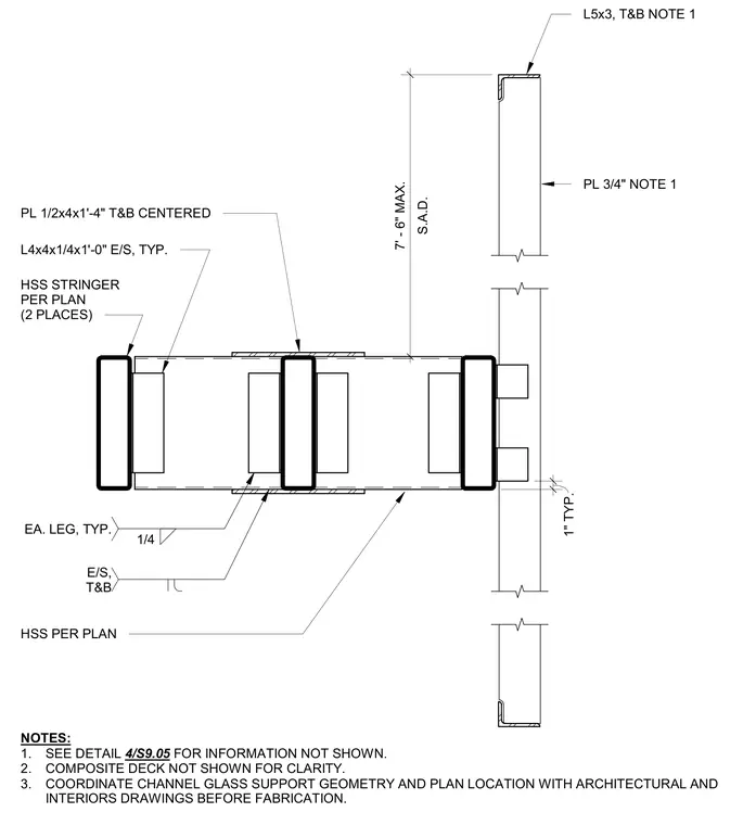
Channel glass is supported vertically by hollow structural section stringers positioned per plan and connected with structural steel framing. A three-quarter-inch plate and top and bottom angles measuring five by three inches are welded to the assembly with quarter-inch fillet welds on each side. Two one-half by four by one-fourteen-inch centered plates and four-by-four-by-one-quarter-inch angles measuring one foot long are welded on each side. Two hollow structural section members are placed per plan in two places with a maximum seven-foot-six-inch dimension. Composite decking is omitted for clarity.
NOTES: 1. SEE DETAIL 4/S9.05 FOR INFORMATION NOT SHOWN. 2. COMPOSITE DECK NOT SHOWN FOR CLARITY. 3. COORDINATE CHANNEL GLASS SUPPORT GEOMETRY AND PLAN LOCATION WITH ARCHITECTURAL AND INTERIORS DRAWINGS BEFORE FABRICATION. 1" TYP. S.A.D. 7' - 6" MAX. HSS STRINGER PER PLAN (2 PLACES) PL 3/4" NOTE 1 L5x3, T&B NOTE 1 EA. LEG, TYP. 1/4 E/S, T&B L4x4x1/4x1'-0" E/S, TYP. PL 1/2x4x1'-4" T&B CENTERED HSS PER PLAN
Members view this detail in full resolution, download the CAD files (SVG, PDF), and can adapt it in the built-in CAD editor — export DXF, DWG, or PDF.
Start membership