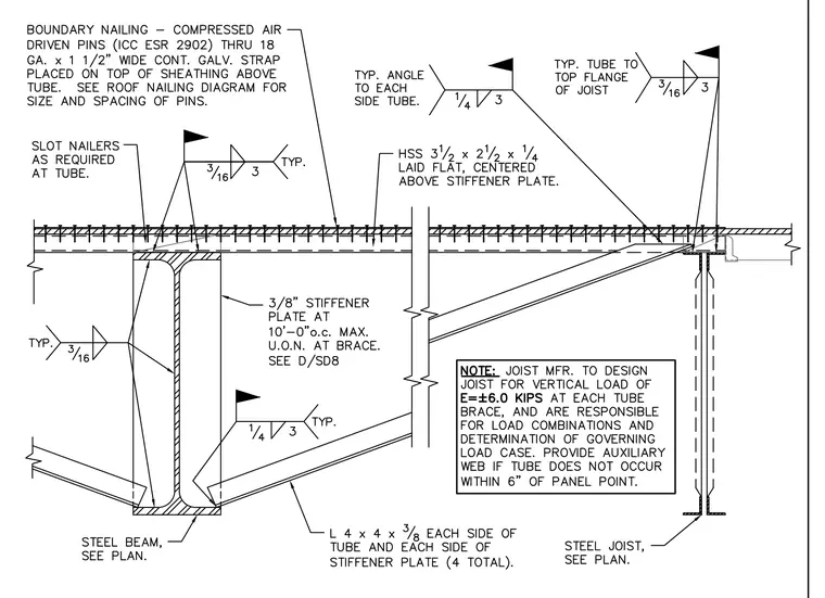
An HSS 3 1/2 x 2 1/2 x 1/4 hollow structural section is laid flat and centered above a 3/8-inch stiffener plate located at 10'-0" o.c. maximum on the supporting steel beam. Angles sized at L 4 x 4 x 3/8 are attached to each side of the tube and each side of the stiffener plate using four total connections, with 1/4-inch fillet welds at 3-inch spacing specified typically. Boundary nailing consisting of compressed air-driven pins per ICC ESR 2902 secures an 18-gauge by 1 1/2-inch wide continuous galvanized strap placed on top of the sheathing above the tube. A steel joist connects at the right with a 3/16-inch fillet weld at 3-inch spacing typical from the tube to the top flange of the joist. A notes block specifies that the joist manufacturer must design the joist for a vertical load of E = +/-6.0 kips at each tube brace and provide an auxiliary web if the tube does not occur within 6 inches of the panel point.
Members view this detail in full resolution, download the CAD files (SVG, PDF), and can adapt it in the built-in CAD editor — export DXF, DWG, or PDF.
Start membership