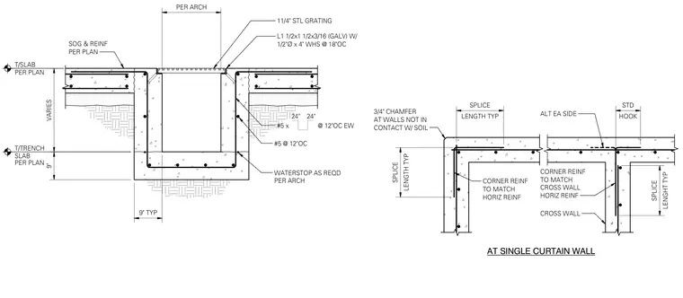
A concrete trench is integrated into a slab on grade, topped with a 1-1/4 inch steel grating supported by galvanized angle sections (L 1-1/2x1-1/2x3/16) anchored with 1/2 inch diameter by 4 inch welded head studs at 18 inches on center. The concrete trench features #5 reinforcing bars spaced at 12 inches on center each way, with a waterstop installed as required per architectural drawings. Adjacent wall corners include standard lap splices, corner reinforcing matching the horizontal wall reinforcing, and a 3/4 inch chamfer at walls not in contact with soil.
AT SINGLE CURTAIN WALL CORNER REINF TO MATCH HORIZ REINF CROSS WALL CORNER REINF TO MATCH CROSS WALL HORIZ REINF 3/4" CHAMFER AT WALLS NOT IN CONTACT W/ SOIL ALT EA SIDE LENGTH TYP SPLICE LENGHT TYP SPLICE HOOK STD LENGTH TYP SPLICE VARIES 9" 9" TYP PER ARCH SOG & REINF PER PLAN 11/4" STL GRATING #5 @ 12"OC WATERSTOP AS REQD PER ARCH L1 1/2x1 1/2x3/16 (GALV) W/ 1/2"Ø x 4" WHS @ 18"OC #5 x @ 12"OC EW T/SLAB PER PLAN T/TRENCH SLAB PER PLAN 24" 24"
Members view this detail in full resolution, download the CAD files (SVG, PDF), and can adapt it in the built-in CAD editor — export DXF, DWG, or PDF.
Start membership