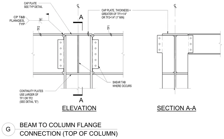
A beam-to-column flange connection at the top of a column incorporates a cap plate welded to the top and bottom flanges, with its thickness sized as the greater of the flange thicknesses plus one-quarter inch, maintaining a one-inch minimum. Continuity plates are aligned inside the column web and sized using the larger of the connecting flange thicknesses. Shear tabs are provided at the web connections where required.
A A BEAM TO COLUMN FLANGE G CONNECTION (TOP OF COLUMN) SECTION A-A ELEVATION CONTINUITY PLATES USE LARGER OF TF1 OR TF2 (SEE DETAIL "E") CAP PLATE, THICKNESS = GREATER OF TF1+1/4" OR TF2+1/4" (1" MIN) TF2 TF1 . CP T&B FLANGES, TYP M CAP PLATE SEE TYP DETAIL SHEAR TAB WHERE OCCURS
Members view this detail in full resolution, download the CAD files (SVG, PDF), and can adapt it in the built-in CAD editor — export DXF, DWG, or PDF.
Start membership