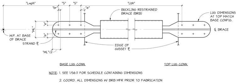
A buckling restrained brace connects to structural supports via welded and bolted end lugs and gusset plates. The assembly features a central strand plate flanked by symmetric lug dimensions matching between top and base configurations. Fastener spacing, edge distances, and working point locations are coordinated with the manufacturer prior to fabrication. Specific dimensions for length, width, and bolt spacing are referenced in a separate schedule.
BASE LUG CONN. TOP LUG CONN. "Lwph" "S" "S" "Lbh" "e" "br" "WL"/2 "WL" "e" BUCKLING RESTRAINED BRACE (BRB) BRACE LUG DIMENSIONS AT TOP MATCH BASE CONFIG. EDGE OF GUSSET W.P. AT BASE OF BRACE STRAND NOTE: 1. SEE 1/S6.11 FOR SCHEDULE CONTAINING DIMENSIONS 2. COORD. ALL DIMENSIONS W/ BRB MFR PRIOR TO FABRICATION "e"
Members view this detail in full resolution, download the CAD files (SVG, PDF), and can adapt it in the built-in CAD editor — export DXF, DWG, or PDF.
Start membership