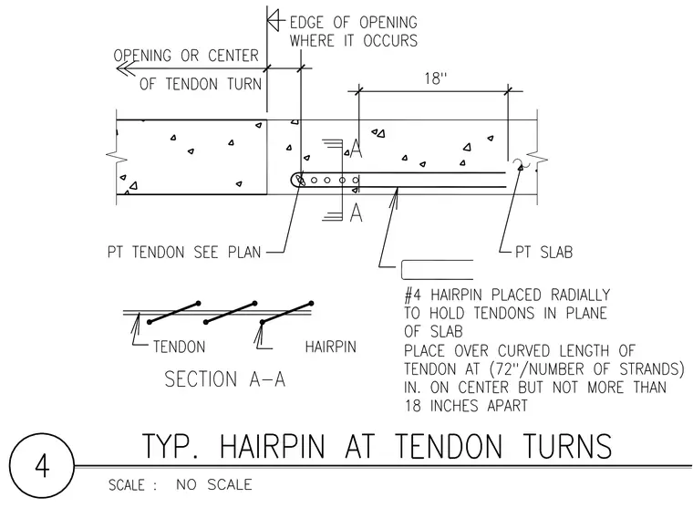
Number 4 hairpins are placed radially to hold post-tensioning tendons in the plane of the concrete slab. The hairpin is placed over the curved length of the tendon at a spacing determined by dividing seventy-two inches by the number of strands, with a maximum spacing of eighteen inches on center. A post-tension tendon is routed around the opening edge per the plan, with dimensions marking eighteen inches from the end of the tendon turn. A small section cut shows the alignment of tendons and hairpins within the slab.
Members view this detail in full resolution, download the CAD files (SVG, PDF), and can adapt it in the built-in CAD editor — export DXF, DWG, or PDF.
Start membership