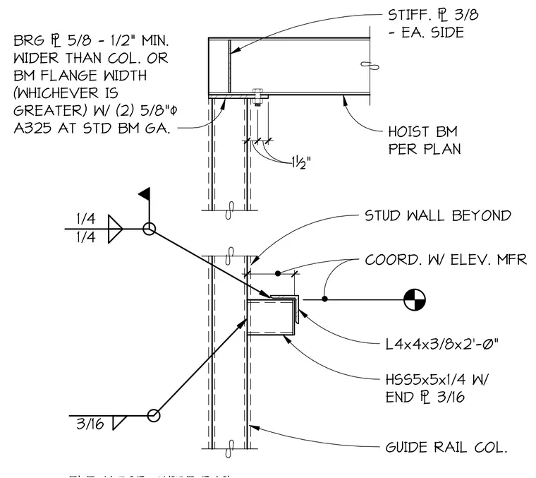
A hoist beam per plan bears on a five-eighths-inch thick bearing plate that extends at least one-half inch wider than the column or beam flange width, whichever is greater, secured with two five-eighths-inch diameter A325 bolts at standard beam gauge. Three-eighths-inch thick stiffener plates are welded to each side of the hoist beam web at the support. Below, a hollow structural section guide rail column of five-by-five-by-one-quarter-inch dimensions with a three-sixteenths-inch end plate connects to a four-by-four-by-three-eighths-inch angle measuring two feet zero inches in length, coordinated with the elevator manufacturer and positioned adjacent to a stud wall beyond.
3/16 GUIDE RAIL COL. HSS5x5x1/4 W/ END # 3/16 STUD WALL BEYOND L4x4x3/8x2'-0" 1/4 1/4 COORD. W/ ELEV. MFR HOIST BM PER PLAN BRG # 5/8 - 1/2" MIN. WIDER THAN COL. OR BM FLANGE WIDTH (WHICHEVER IS GREATER) W/ (2) 5/8"2 A325 AT STD BM GA. STIFF. # 3/8 - EA. SIDE 1½" 1½"
Members view this detail in full resolution, download the CAD files (SVG, PDF), and can adapt it in the built-in CAD editor — export DXF, DWG, or PDF.
Start membership