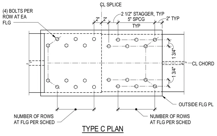
A Type C chord flange splice features outside flange plates connected with four bolts per row at each flange. The layout incorporates a center splice line with specified bolt edge distances and a two and one-half inch typical stagger. Bolt spacing is set at five inches typical with gauge dimensions measuring one and three-quarters inches from the chord centerline. The number of rows at the flange is determined per the structural schedule.
TYPE C PLAN (4) BOLTS PER ROW AT EA FLG CL SPLICE NUMBER OF ROWS AT FLG PER SCHED NUMBER OF ROWS AT FLG PER SCHED 10" 10" OUTSIDE FLG PL 2" 2" 2 1/2" STAGGER, TYP TYP 5" SPCG 2" TYP CL CHORD 1 3/4" 1 3/4"
Members view this detail in full resolution, download the CAD files (SVG, PDF), and can adapt it in the built-in CAD editor — export DXF, DWG, or PDF.
Start membership