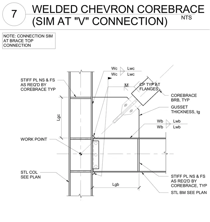
A buckling-restrained brace connects to a structural steel column and beam frame via a gusset plate and welded connections. Stiffener plates are placed near side and far side on the column and beam as required by the manufacturer. Welds are specified with variable sizes and lengths along the column and beam flanges and web. A work point is established at the intersection of the framing centerlines.
CP TYP AT FLANGES STIFF PL NS & FS AS REQ'D BY COREBRACE TYP COREBRACE BRB, TYP Wc Lwc Wc Lwc Wb Lwb Wb Lwb GUSSET THICKNESS, tg STIFF PL NS & FS AS REQ'D BY COREBRACE, TYP STL BM SEE PLAN WORK POINT STL COL SEE PLAN Lgb Lgc NOTE: CONNECTION SIM AT BRACE TOP CONNECTION M NTS 7 WELDED CHEVRON COREBRACE (SIM AT "V" CONNECTION)
Members view this detail in full resolution, download the CAD files (SVG, PDF), and can adapt it in the built-in CAD editor — export DXF, DWG, or PDF.
Start membership