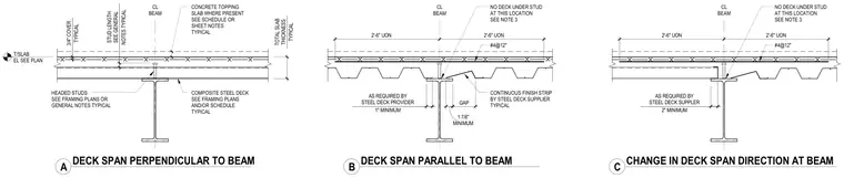
Composite floor slab assembly supported on structural steel framing, featuring headed shear studs welded through a composite steel deck. A concrete topping slab sits above the steel deck with specified concrete cover and reinforcing bars spaced at twelve inches on center. The assembly includes configurations for deck spanning perpendicular to the beam, parallel to the beam with required gaps and continuous finish strips, and a change in deck span direction at the beam support. Stud lengths, slab thickness, and stud placement are detailed per framing plans and general notes.
HEADED STUDS SEE FRAMING PLANS OR GENERAL NOTES TYPICAL COMPOSITE STEEL DECK SEE FRAMING PLANS AND/OR SCHEDULE TYPICAL TYPICAL TOTAL SLAB THICKNESS T/SLAB EL SEE PLAN CONCRETE TOPPING SLAB WHERE PRESENT SEE SCHEDULE OR SHEET NOTES TYPICAL NOTES TYPICAL STUD LENGTH SEE GENERAL CONTINUOUS FINISH STRIP BY STEEL DECK SUPPLIER TYPICAL 2'-6" UON 2'-6" UON #4@12" NO DECK UNDER STUD AT THIS LOCATION SEE NOTE 3 MINIMUM 1 7/8" GAP 2'-6" UON 2'-6" UON 2" MINIMUM AS REQUIRED BY STEEL DECK SUPPLER 1" MINIMUM AS REQUIRED BY STEEL DECK PROVIDER TYPICAL 3/4" COVER 0' - 1 1/2" #4@12" NO DECK UNDER STUD AT THIS LOCATION SEE NOTE 3 CL BEAM CL BEAM CL BEAM A DECK SPAN PERPENDICULAR TO BEAM B DECK SPAN PARALLEL TO BEAM C CHANGE IN DECK SPAN DIRECTION AT BEAM
Members view this detail in full resolution, download the CAD files (SVG, PDF), and can adapt it in the built-in CAD editor — export DXF, DWG, or PDF.
Start membership