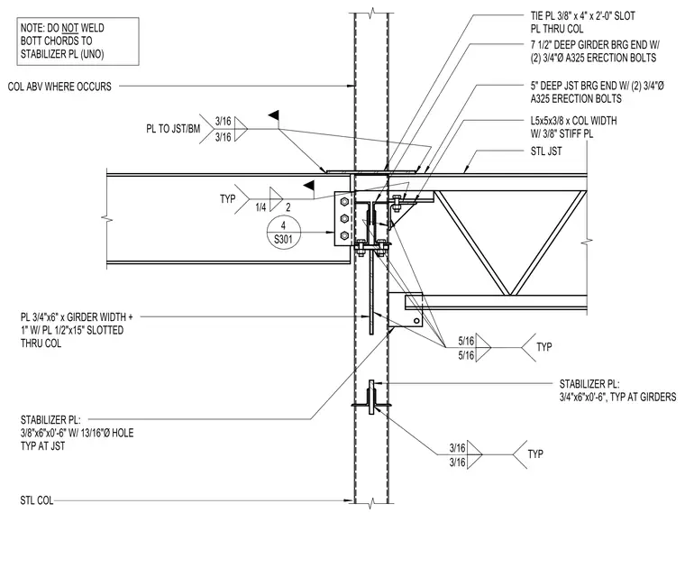
A 3/8-inch by 4-inch by 2-foot-0-inch tie plate slots through the steel column and is welded to the joist and beam. The 7-1/2-inch deep girder bearing end connects with two 3/4-inch diameter A325 erection bolts. The 5-inch deep steel joist bearing end connects with two 3/4-inch diameter A325 erection bolts using an L5x5x3/8 angle matching the column width with a 3/8-inch stiffener plate. A 3/4-inch by 6-inch by girder width plus 1-inch plate slots through the column alongside a 1/2-inch by 15-inch plate. Stabilizer plates measuring 3/4-inch by 6-inch by 0-foot-6-inch are used typically at girders, and 3/8-inch by 6-inch by 0-foot-6-inch stabilizer plates with 13/16-inch diameter holes are used typically at joists. Bottom chords are left unwelded to the stabilizer plate unless noted otherwise.
NOTE: DO NOT WELD BOTT CHORDS TO STABILIZER PL (UNO) STABILIZER PL: 3/4"x6"x0'-6", TYP AT GIRDERS L5x5x3/8 x COL WIDTH W/ 3/8" STIFF PL PL 3/4"x6" x GIRDER WIDTH + 1" W/ PL 1/2"x15" SLOTTED THRU COL STABILIZER PL: 3/8"x6"x0'-6" W/ 13/16"Ø HOLE TYP AT JST 5" DEEP JST BRG END W/ (2) 3/4"Ø A325 ERECTION BOLTS 7 1/2" DEEP GIRDER BRG END W/ (2) 3/4"Ø A325 ERECTION BOLTS TYP 1/4 2 TYP 3/16 3/16 TYP 5/16 5/16 STL COL STL JST S301 4 TIE PL 3/8" x 4" x 2'-0" SLOT PL THRU COL 3/16 PL TO JST/BM 3/16 COL ABV WHERE OCCURS
Members view this detail in full resolution, download the CAD files (SVG, PDF), and can adapt it in the built-in CAD editor — export DXF, DWG, or PDF.
Start membership