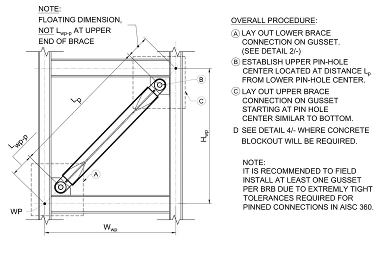
This diagram details the layout procedure for buckling-restrained brace (BRB) connections between structural steel columns and beams. The installation process begins by laying out the lower brace connection on the gusset plate as referenced in detail. The upper pin-hole center is then established at a specific distance Lp from the lower pin-hole center, using a floating dimension at the upper end of the brace rather than the work point-to-work point distance Lwp-p. The upper brace connection is subsequently laid out on the gusset starting at the pin hole center similarly to the bottom. A concrete blockout is required at the designated location per detail references. Field installation of at least one gusset per BRB is recommended due to the extremely tight tolerances required for pinned connections in accordance with AISC 360.
A LAY OUT LOWER BRACE CONNECTION ON GUSSET. (SEE DETAIL 2/-) OVERALL PROCEDURE: B ESTABLISH UPPER PIN-HOLE CENTER LOCATED AT DISTANCE L p FROM LOWER PIN-HOLE CENTER. C LAY OUT UPPER BRACE CONNECTION ON GUSSET STARTING AT PIN HOLE CENTER SIMILAR TO BOTTOM. IT IS RECOMMENDED TO FIELD INSTALL AT LEAST ONE GUSSET PER BRB DUE TO EXTREMLY TIGHT TOLERANCES REQUIRED FOR PINNED CONNECTIONS IN AISC 360. WP Lp L wp-p NOTE: FLOATING DIMENSION, NOT L wp-p AT UPPER END OF BRACE B W wp H wp NOTE: C A SEE DETAIL 4/- WHERE CONCRETE BLOCKOUT WILL BE REQUIRED. D
Members view this detail in full resolution, download the CAD files (SVG, PDF), and can adapt it in the built-in CAD editor — export DXF, DWG, or PDF.
Start membership