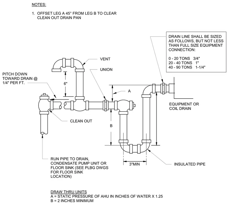
A cooling coil condensate trap piping configuration for draw-thru air handling units. Dimension A is determined by multiplying the static pressure of the air handling unit in inches of water by 1.25, while dimension B requires a minimum of 2 inches with a 3-inch minimum horizontal run. The assembly incorporates unions for maintenance, a vent upstream of the trap, and a cleanout. Drain lines must pitch downward toward the drain at one-quarter inch per foot and are sized according to equipment tonnage ranging from three-quarters of an inch to one and one-quarter inches.
EQUIPMENT OR COIL DRAIN 6" 3"MIN B NOTES: 1. OFFSET LEG A 45° FROM LEG B TO CLEAR CLEAN OUT DRAIN PAN DRAW THRU UNITS A = STATIC PRESSURE OF AHU IN INCHES OF WATER X 1.25 B = 2 INCHES MINIMUM INSULATED PIPE RUN PIPE TO DRAIN, CONDENSATE PUMP UNIT OR FLOOR SINK (SEE PLBG DWGS FOR FLOOR SINK LOCATION) CLEAN OUT PITCH DOWN TOWARD DRAIN @ 1/4" PER FT. VENT A UNION DRAIN LINE SHALL BE SIZED AS FOLLOWS, BUT NOT LESS THAN FULL SIZE EQUIPMENT CONNECTION: 0 - 20 TONS 3/4" 20 - 40 TONS 1" 40 - 90 TONS 1-1/4"
Members view this detail in full resolution, download the CAD files (SVG, PDF), and can adapt it in the built-in CAD editor — export DXF, DWG, or PDF.
Start membership