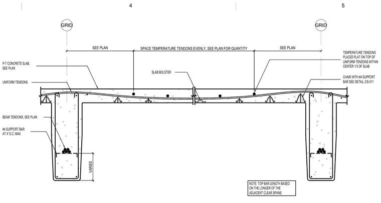
A typical one-way post-tensioned concrete slab is supported by cast-in-place concrete beams between grid lines. The assembly incorporates uniform tendons and temperature tendons placed flat on top of uniform tendons within the center one-third of the slab. Slab bolsters and chairs with number 4 support bars spaced at a maximum of four feet on center support the reinforcement. Beam tendons are bundled in the bottom of the concrete beam section, which varies in depth as specified on the plan. Top bar lengths are determined based on the longer of the adjacent clear spans.
GRID GRID CHAIR WITH #4 SUPPORT BAR SEE DETAIL 2/S-511 SLAB BOLSTER TEMPERATURE TENDONS PLACED FLAT ON TOP OF UNIFORM TENDONS WITHIN UNIFORM TENDONS CENTER 1/3 OF SLAB NOTE: TOP BAR LENGTH BASED ON THE LONGER OF THE ADJACENT CLEAR SPANS #4 SUPPORT BAR AT 4' O.C. MAX BEAM TENDONS, SEE PLAN P-T CONCRETE SLAB, SEE PLAN VARIES SEE PLAN SPACE TEMPERATURE TENDONS EVENLY, SEE PLAN FOR QUANTITY SEE PLAN 4 5
Members view this detail in full resolution, download the CAD files (SVG, PDF), and can adapt it in the built-in CAD editor — export DXF, DWG, or PDF.
Start membership