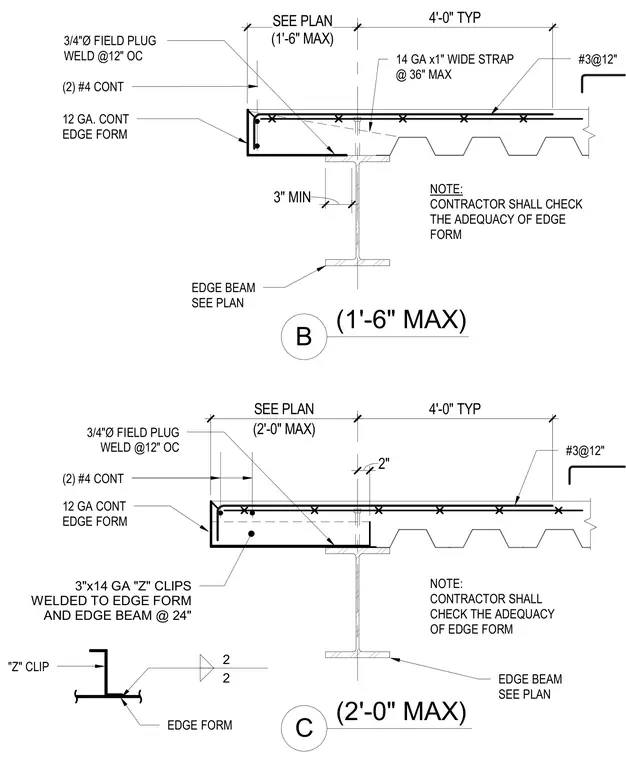
The assembly consists of a concrete slab on metal deck supported by a steel edge beam, detailed with a continuous twelve-gauge metal edge form. Two continuous number four rebars run longitudinally along the perimeter, supplemented by number three bars spaced at twelve inches on center. The edge form is anchored with three-quarter-inch diameter field plug welds spaced at twelve inches on center, and secured using either fourteen-gauge by one-inch wide straps at thirty-six inches maximum spacing or three-inch by fourteen-gauge Z-clips welded to the edge form and edge beam at twenty-four inches on center. A minimum three-inch bearing is provided on the structural steel beam, which is sized per plan. A note instructs the contractor to verify the adequacy of the edge form.
(1'-6" MAX) B #3@12" 12 GA. CONT EDGE FORM NOTE: CONTRACTOR SHALL CHECK THE ADEQUACY OF EDGE FORM 14 GA x1" WIDE STRAP @ 36" MAX (1'-6" MAX) SEE PLAN (2'-0" MAX) C #3@12" 3"x14 GA "Z" CLIPS WELDED TO EDGE FORM AND EDGE BEAM @ 24" "Z" CLIP NOTE: CONTRACTOR SHALL CHECK THE ADEQUACY OF EDGE FORM EDGE BEAM SEE PLAN EDGE FORM (2) #4 CONT 12 GA CONT EDGE FORM 3/4"Ø FIELD PLUG WELD @12" OC 4'-0" TYP (2'-0" MAX) SEE PLAN EDGE BEAM SEE PLAN 4'-0" TYP 3" MIN 2 2 2" (2) #4 CONT 3/4"Ø FIELD PLUG WELD @12" OC
Members view this detail in full resolution, download the CAD files (SVG, PDF), and can adapt it in the built-in CAD editor — export DXF, DWG, or PDF.
Start membership