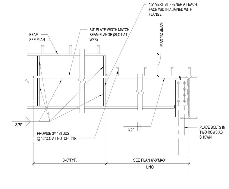
The steel beam framing connects to a support with bolts arranged in two vertical rows. A five-eighths-inch plate with a slotted web matches the beam flange width. Vertical stiffeners at each face align with the flange, maintaining a maximum depth of one-half of the beam. Three-quarter-inch studs are provided at twelve inches on center at the notch. Maximum spacing dimensions are indicated as three feet typical and six feet maximum unless noted otherwise.
PLACE BOLTS IN TWO ROWS AS SHOWN BEAM SEE PLAN 5/8" PLATE WIDTH MATCH BEAM FLANGE (SLOT AT WEB) MAX 1/2 BEAM 3'-0"TYP. UNO SEE PLAN 6'-0"MAX. 3/8" 1/2" 1/2" VERT STIFFENER AT EACH FACE WIDTH ALIGNED WITH FLANGE PROVIDE 3/4" STUDS @ 12"O.C AT NOTCH, TYP.
Members view this detail in full resolution, download the CAD files (SVG, PDF), and can adapt it in the built-in CAD editor — export DXF, DWG, or PDF.
Start membership