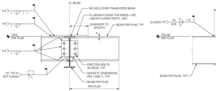
A structural steel cantilever beam connects to a supporting transverse beam using a bolted shear plate and a top plate sized per plan. The top plate is left unwelded directly over the transverse beam centerline and incorporates specified fillet welds around its perimeter. Erection bolts are provided as required for temporary alignment before final welding. Shear plate dimensions follow engineering standards, with weld sizes and locations detailed for the top and bottom flanges.
[ ] [ ] TYP [ ] TYP CP, TYP AT BOT FLANGE [ ] TYP CL BEAM NO WELD OVER TRANSVERSE BEAM PL=(BEAM FLANGE THICKNESS +1/8") x (BEAM FLANGE WIDTH - 3/4") BEAM PER PLAN, TYP ERECTION BOLTS AS REQD, TYP SHEAR PL DIMENSIONS PER 17/S6.11, TYP BEAM PER PLAN PER PLAN tf SPECIFY] [ENGINEER TO T/STL PER PLAN BEAM PER PLAN, TYP T/SLAB PER PLAN 5/16 1/4 1-12 (3) SIDES TYP
Members view this detail in full resolution, download the CAD files (SVG, PDF), and can adapt it in the built-in CAD editor — export DXF, DWG, or PDF.
Start membership