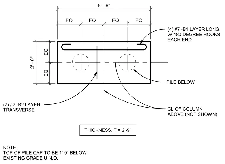
This structural detail shows a concrete pile cap plan measuring five feet six inches by two feet six inches with a thickness of two feet nine inches. The assembly includes four number seven longitudinal bars in the B1 layer with one hundred eighty degree hooks at each end, and seven number seven transverse bars in the B2 layer. Piles are located below the cap symmetrically spaced with equal dimensions between centerlines. The center line of the column above is aligned with the cap centroid. Notes specify that the top of the pile cap is to be placed one foot below existing grade unless otherwise noted.
CL OF COLUMN ABOVE (NOT SHOWN) (4) #7 -B1 LAYER LONG. w/ 180 DEGREE HOOKS EACH END THICKNESS, T = 2'-9" (7) #7 -B2 LAYER TRANSVERSE PILE BELOW 5' - 6" 2' - 6" EQ EQ EQ EQ EQ EQ NOTE: TOP OF PILE CAP TO BE 1'-0" BELOW EXISTING GRADE U.N.O.
Members view this detail in full resolution, download the CAD files (SVG, PDF), and can adapt it in the built-in CAD editor — export DXF, DWG, or PDF.
Start membership