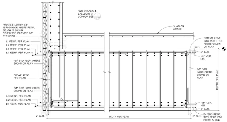
This structural section details the concrete footing and slab on grade connection with specified reinforcing bar sizes and layouts per plan. The foundation wall incorporates top and bottom reinforcing layers denoted as t.1 through t.4 and b.1 through b.3, utilizing ninety-degree standard hooks or Lenton D6 terminators where indicated. Shear reinforcement is spaced per plan throughout the footing width and depth, maintaining specified clearances including two-inch clear cover at the sides and bottom. Reinforcing bars extend into perpendicular footings where shown on plan, and the slab on grade bears directly above the footing assembly.
FOR DETAILS & CALLOUTS IN COMMON SEE 1 S22-00 T.O.F. SLAB ON GRADE 90° STD HOOK WHERE SHOWN ON PLAN t.1 REINF. PER PLAN t.2 REINF. PER PLAN t.4 REINF. PER PLAN b.3 REINF. PER PLAN b.2 REINF. PER PLAN b.1 REINF. PER PLAN 90° STD HOOK WHERE SHOWN ON PLAN t.3 REINF. PER PLAN PROVIDE LENTON D6 TERMINATOR WHERE REINF. BELOW IS SHOWN OTHERWISE, PROVIDE 90° STD HOOK WIDTH PER PLAN 2" CLR. DEPTH PER PLAN 90° STD HOOK WHERE SHOWN ON PLAN EXTEND REINF. INTO PERP. FTG WHERE SHOWN ON PLAN EXTEND REINF. INTO PERP. FTG WHERE SHOWN 3" CLR. 2" CLR. 2" CLR. SHEAR REINF. PER PLAN 2 1 / 8" 1 1 /2" "db" CLR. MIN. 3" 1 5/ 8" "db" CLR. MIN.
Members view this detail in full resolution, download the CAD files (SVG, PDF), and can adapt it in the built-in CAD editor — export DXF, DWG, or PDF.
Start membership