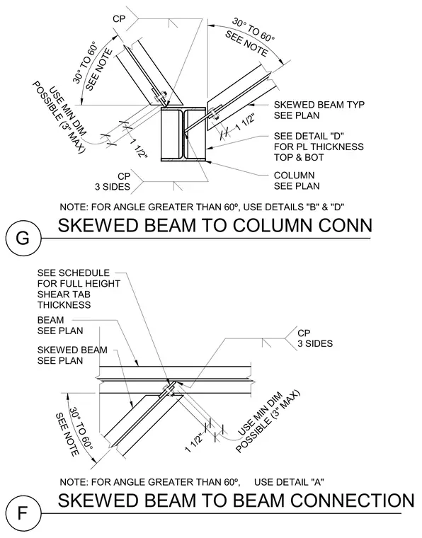
Skewed steel beam connections frame into both columns and supporting beams with skewed angles ranging from 30 to 60 degrees. A skewed beam frames into a column flange with a shear tab and corner plates, maintaining one and one-half inch clearances and three-inch maximum dimensions. A skewed beam frames into a supporting beam web utilizing a full-height shear tab whose thickness is determined by the structural schedule. Additional notes guide fabricators on specific plate thicknesses, weld configurations on three sides, and alternative detail references for angles greater than 60 degrees.
SKEWED BEAM TO BEAM CONNECTION F SKEWED BEAM SEE PLAN BEAM SEE PLAN 1 1/2" CP 3 SIDES POSSIBLE (3" MAX) USE MIN DIM SEE SCHEDULE FOR FULL HEIGHT SHEAR TAB THICKNESS SKEWED BEAM TO COLUMN CONN G 1 1/2" CP SKEWED BEAM TYP SEE PLAN COLUMN SEE PLAN SEE DETAIL "D" FOR PL THICKNESS TOP & BOT 1 1/2" POSSIBLE (3" MAX) USE MIN DIM SEE NOTE 30° TO 60° SEE NOTE 30° TO 60° CP 3 SIDES NOTE: FOR ANGLE GREATER THAN 60º, USE DETAILS "B" & "D" NOTE: FOR ANGLE GREATER THAN 60º, USE DETAIL "A" SEE NOTE 30° TO 60°
Members view this detail in full resolution, download the CAD files (SVG, PDF), and can adapt it in the built-in CAD editor — export DXF, DWG, or PDF.
Start membership