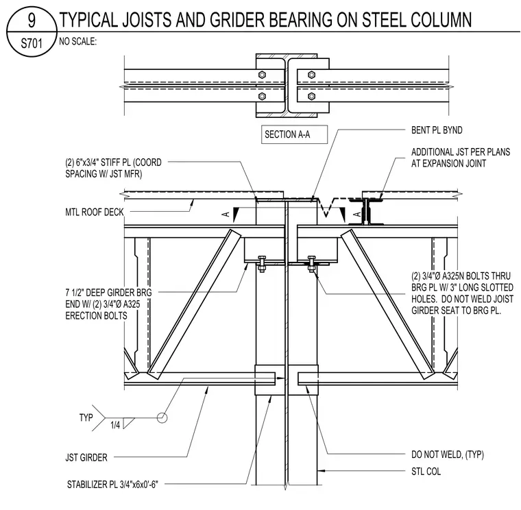
A steel column supports a seven-and-a-half-inch deep joist girder bearing end connected with two three-quarter-inch diameter A325 erection bolts. Two six-inch by three-quarter-inch stiffener plates are coordinated for spacing with the joist manufacturer. The connection utilizes two three-quarter-inch diameter A325N bolts through the bearing plate with three-inch long slotted holes, and the joist girder seat is left unwelded to the bearing plate. A metal roof deck is tied across with a three-quarter-inch by six-inch by zero-foot-six-inch stabilizer plate that remains unwelded. Additional joists are located per plans at the expansion joint alongside a bent plate beyond section A-A.
A A STL COL MTL ROOF DECK STABILIZER PL 3/4"x6x0'-6" DO NOT WELD, (TYP) (2) 6"x3/4" STIFF PL (COORD SPACING W/ JST MFR) 7 1/2" DEEP GIRDER BRG END W/ (2) 3/4"Ø A325 ERECTION BOLTS JST GIRDER TYP 1/4 (2) 3/4"Ø A325N BOLTS THRU BRG PL W/ 3" LONG SLOTTED HOLES. DO NOT WELD JOIST GIRDER SEAT TO BRG PL. ADDITIONAL JST PER PLANS AT EXPANSION JOINT BENT PL BYND SECTION A-A NO SCALE: S701 9 TYPICAL JOISTS AND GRIDER BEARING ON STEEL COLUMN
Members view this detail in full resolution, download the CAD files (SVG, PDF), and can adapt it in the built-in CAD editor — export DXF, DWG, or PDF.
Start membership