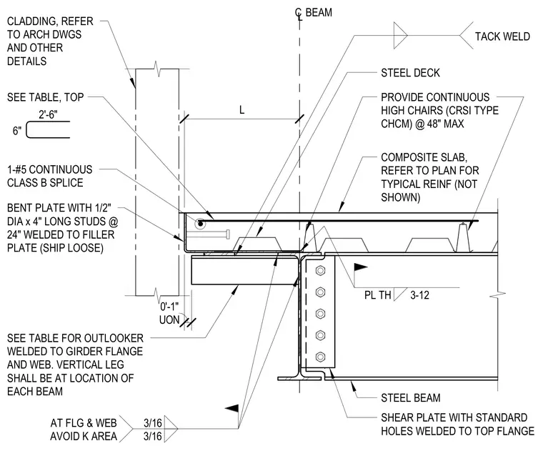
An outlooker beam frames into the girder flange and web with a three-sixteenths inch fillet weld at the flange and web, avoiding the K area of the wide flange section. A steel beam connects via a shear plate with standard holes welded to the top flange. A bent plate with half-inch diameter by four-inch long studs spaced at twenty-four inches on center is welded to a filler plate and shipped loose. A composite slab bears on the steel deck, reinforced with one number five continuous rebar with a class B splice and supported by continuous high chairs at forty-eight inches maximum spacing. Cladding aligns at the edge of the slab per architectural drawings.
3/16 3/16 AT FLG & WEB AVOID K AREA BENT PLATE WITH 1/2" DIA x 4" LONG STUDS @ 24" WELDED TO FILLER PLATE (SHIP LOOSE) SEE TABLE, TOP 1-#5 CONTINUOUS CLASS B SPLICE 2'-6" 6" PROVIDE CONTINUOUS HIGH CHAIRS (CRSI TYPE CHCM) @ 48" MAX CLADDING, REFER TO ARCH DWGS AND OTHER DETAILS L PL TH 3-12 COMPOSITE SLAB, REFER TO PLAN FOR TYPICAL REINF (NOT SHOWN) C L BEAM TACK WELD UON 0'-1" STEEL BEAM STEEL DECK SHEAR PLATE WITH STANDARD HOLES WELDED TO TOP FLANGE SEE TABLE FOR OUTLOOKER WELDED TO GIRDER FLANGE AND WEB. VERTICAL LEG SHALL BE AT LOCATION OF EACH BEAM
Members view this detail in full resolution, download the CAD files (SVG, PDF), and can adapt it in the built-in CAD editor — export DXF, DWG, or PDF.
Start membership