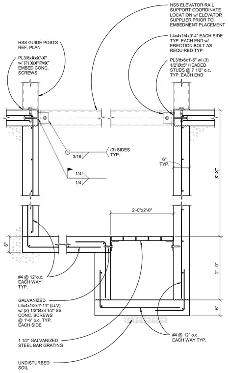
A concrete elevator pit rests on undisturbed soil, reinforced with number four rebar spaced at twelve inches on center each way. The pit walls feature embedded three-eighths-inch by six-inch by one-foot six-inch plates with three half-inch diameter by five-inch headed studs at seven and a half inches on center. Galvanized angles measuring four by four by one-quarter inches and four by four by one-half inches are anchored with stainless steel concrete screws to support the steel bar grating and hollow structural section elevator rail supports. HSS guide posts connect to the foundation via base plates secured with concrete screws and welded with three-sixteenths and one-quarter-inch fillet welds on three sides. A depressed sump pit sits adjacent to the main elevator pit, similarly reinforced with number four rebar at twelve inches on center and covered with a one-and-a-half-inch galvanized steel bar grating.
#4 @ 12'' o.c. EACH WAY TYP. #4 @ 12''o.c. EACH WAY TYP. UNDISTURBED SOIL HSS ELEVATOR RAIL SUPPORT COORDINATE LOCATION w/ ELEVATOR SUPPLIER PRIOR TO EMBEDMENT PLACEMENT GALVANIZED L4x4x1/2x1'-11" (LLV) w/ (2) 1/2"Øx3 1/2" SS CONC. SCREWS @ 1'-6" o.c. TYP. EACH SIDE 1 1/2" GALVANIZED STEEL BAR GRATING 2'-0"x2'-0" TYP. 6" L4x4x1/4x0'-4" EACH SIDE TYP. EACH END w/ ERECTION BOLT AS REQUIRED TYP. PL3/8x6x1'-6" w/ (3) 1/2"Øx5" HEADED STUDS @ 7 1/2" o.c. TYP. EACH END 6" 2' - 0" X'-X" 3/16 (3) SIDES TYP. 1/4 1/4 6" HSS GUIDE POSTS REF. PLAN PL3/8x XxX'-X" w/ (2) X/X" Øx X " EMBED CONC. SCREWS
Members view this detail in full resolution, download the CAD files (SVG, PDF), and can adapt it in the built-in CAD editor — export DXF, DWG, or PDF.
Start membership