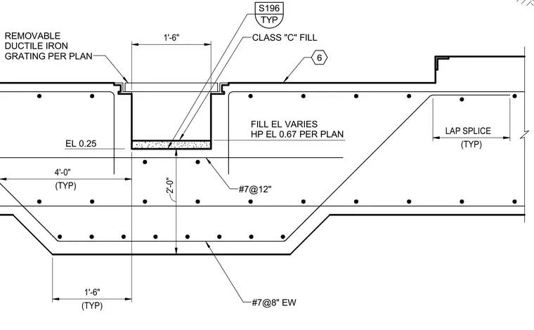
A cast-in-place concrete trench features a removable ductile iron grating set within a recessed frame, with class C fill placed at a variable elevation per plan. The surrounding concrete slab is reinforced with number 7 reinforcing bars spaced at twelve inches on center and number 7 bars at eight inches each way typically. A lap splice is detailed within the slab reinforcement zone alongside dimensional callouts indicating a two-foot trench depth and a one-foot six-inch width.
1'-6" 6 #7@12" CLASS "C" FILL FILL EL VARIES HP EL 0.67 PER PLAN REMOVABLE DUCTILE IRON GRATING PER PLAN EL 0.25 (TYP) 4'-0" TYP S196 (TYP) 1'-6" 2'-0" #7@8" EW (TYP) LAP SPLICE
Members view this detail in full resolution, download the CAD files (SVG, PDF), and can adapt it in the built-in CAD editor — export DXF, DWG, or PDF.
Start membership