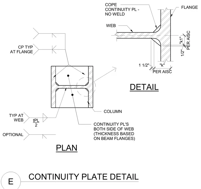
Continuity plates are positioned on both sides of the column web with thicknesses based on the connecting beam flanges. The column web features a cope detail with no weld specified at a distance of one-half inch per AISC dimension k1, while other dimensions follow AISC dimension k and one and one-half inches. Continuity plates at the flange are marked typical, and optional continuity plates at the web are detailed with a plate thickness equal to tPL over two.
DETAIL PLAN CONTINUITY PLATE DETAIL E COLUMN WEB FLANGE COPE CONTINUITY PL - NO WELD 1/2" PER AISC "k1" 1 1/2" PER AISC "k" CONTINUITY PL'S BOTH SIDE OF WEB (THICKNESS BASED ON BEAM FLANGES) OPTIONAL TYP AT WEB tPL 2 CP TYP AT FLANGE
Members view this detail in full resolution, download the CAD files (SVG, PDF), and can adapt it in the built-in CAD editor — export DXF, DWG, or PDF.
Start membership