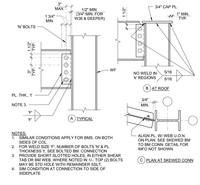
A wide flange beam connects to the flange of a wide flange column using a single plate shear tab welded to the column face and bolted to the beam web. The connection includes a three-quarter-inch thick cap plate welded to the top of the column and beam with five-sixteenth-inch fillet welds, leaving the web k-regions unwelded. Short slotted holes are provided in either the shear tab or the beam web with standard holes for the top two bolts where indicated. Similar conditions apply for beams on both sides of the column and to the side of a sideplate. Plan details show alignment of the plate with the web and skewed beam connection geometry.
1 1/2" TYP. 3" MAX. 3/4" 1" MIN. TYP. 1 1/2" 1/2" MIN. (3/4" MIN. FOR W36 & DEEPER) 3" TYP. 1 3/4" MIN. 'F' 'F' 5/16 5/16 NO WELD IN 'k' REGIONS ALIGN PL. W/ WEB U.O.N. ON PLAN. SEE SKEWED BM TO BM CONN. DETAIL FOR INFO NOT SHOWN 3/4" CAP PL. NOTES: 1. SIMILAR CONDITIONS APPLY FOR BMS. ON BOTH SIDES OF COL. 2. FOR WELD SIZE 'F', NUMBER OF BOLTS 'N' & PL. THICKNESS 't', SEE BOLTED BM. CONNECTION 3. PROVIDE SHORT SLOTTED HOLES, IN EITHER SHEAR TAB OR BM WEB, WHERE NOTED IN 1/-. TOP (2) BOLTS MAY BE STD HOLE WITH REMAINDER SSLT. 4. SIM CONDITION AT CONNECTION TO SIDE OF SIDEPLATE PL. THK., 't' A WF 'N' BOLTS TYPICAL NOTE 3. MIN. B AT ROOF C PLAN AT SKEWED CONN
Members view this detail in full resolution, download the CAD files (SVG, PDF), and can adapt it in the built-in CAD editor — export DXF, DWG, or PDF.
Start membership