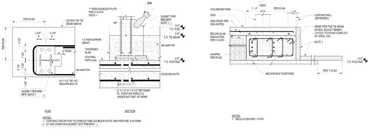
A buckling restrained brace frame base plate connection anchors to a reinforced concrete footing and tie beam. The assembly features a two-inch base plate secured by four one-and-a-half-inch Grade 105 anchor bolts equipped with leveling nuts. A one-and-a-half-inch layer of non-shrink grout is detailed beneath the base plate over a thickened slab. A retainer plate measuring two inches by one foot by one foot eight-and-a-half inches is positioned directly under the bottom mat of reinforcement. Number eight hairpins provide additional confinement at the foundation tie beam per the structural schedule.
1 3/4" 2 1/2" 7 3/4" 7 3/4" 2 1/2" 4" 2 3/4" 2 3/4" 4" (4) 1-1/2" GR 105 ANCHOR BOLTS 2" BASE PL GUSSET PER BRB MFR, NOTE 1 GUSSET PER BRB MFR, NOTE 1 2" X 1'-0" X 1'-8 1/2" RETAINER PL, POSITION DIRECTLY UNDER BOT MAT OF REINF BRB 1.5" NON-SHRINK GROUT FOOTING PER PLAN NOTES: 1. CONTRACTOR OPTION TO FOREGO WEB DOUBLER PLATE AND PROVIDE A W10X88. 2. AT SIM CONDITION GUSSET NOT PRESENT. THICKENED SLAB EXTENT OF TIE BEAM ABOVE #8 HAIR PIN PLAN SECTION WP 1" WEB DOUBLER PLATE PER NOTE 1 PER PLAN PER PLAN #8 HAIR PIN -2'-0" T.O. FOOTING 0'-6" T.O. TIE BEAM 0'-0" T.O. SOG LEVELING NUTS 1 1 1 / 2 S-510 SOG GRID COLUMN BEYOND PER PLAN 1' - 0" ANCHOR BOLTS BEYOND REINF PER FDN TIE BEAM SCHED, ADJUST REBAR LAYOUT TO AVOID CONFLICT W/ STEEL COL SOG REINF PER GEN NOTES NOTE 1 / 1 S-501 PER NOTES: 1. INSULATION PER BELOW SLAB INSULATION PER / 1 S-501 -2'-0" T.O. FOOTING CURTAIN WALL (DEFERRED) HAIRPIN PER PLAN / 1 S-501
Members view this detail in full resolution, download the CAD files (SVG, PDF), and can adapt it in the built-in CAD editor — export DXF, DWG, or PDF.
Start membership