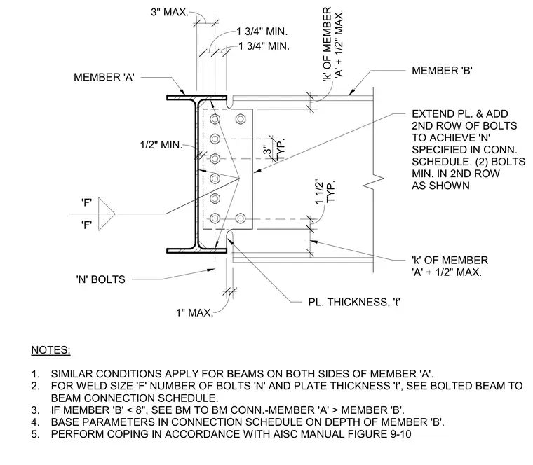
A standard beam-to-beam connection frames a supported member into a primary supporting member. A connection plate of thickness t is welded to the supporting member web using specified fillet welds labeled F, while the supported member web is fastened with N bolts configured with standard edge and spacing dimensions. When required for capacity, the plate is extended to accommodate a second vertical row containing a minimum of two bolts. Coping of the supported beam flange follows AISC manual guidelines to clear the supporting member geometry. Similar connection conditions apply when framing beams to both sides of the main member.
1. DETAIL APPLIES TO BM TO BM CONNECTIONS FOR W12x AND LARGER MEMBERS NOTED MEMBER 'B' MEMBER 'A' 'N' BOLTS PL. THICKNESS, 't' NOTES: 1. SIMILAR CONDITIONS APPLY FOR BEAMS ON BOTH SIDES OF MEMBER 'A'. 2. FOR WELD SIZE 'F' NUMBER OF BOLTS 'N' AND PLATE THICKNESS 't', SEE BOLTED BEAM TO BEAM CONNECTION SCHEDULE. 3. IF MEMBER 'B' < 8", SEE BM TO BM CONN.-MEMBER 'A' > MEMBER 'B'. 4. BASE PARAMETERS IN CONNECTION SCHEDULE ON DEPTH OF MEMBER 'B'. 5. PERFORM COPING IN ACCORDANCE WITH AISC MANUAL FIGURE 9-10 TYP. 3" TYP. 1 1/2" 1 3/4" MIN. 1 3/4" MIN. 3" MAX. 3 139/256" 1" MAX. 1/2" MIN. EXTEND PL. & ADD 2ND ROW OF BOLTS TO ACHIEVE 'N' SPECIFIED IN CONN. SCHEDULE. (2) BOLTS MIN. IN 2ND ROW AS SHOWN 'k' OF MEMBER 'A' + 1/2" MAX. 'A' + 1/2" MAX. 'k' OF MEMBER 'F' 'F'
Members view this detail in full resolution, download the CAD files (SVG, PDF), and can adapt it in the built-in CAD editor — export DXF, DWG, or PDF.
Start membership