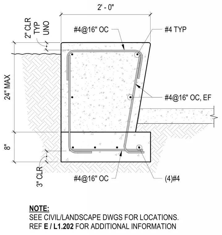
This cast-in-place concrete retaining seatwall features a width of two feet and a maximum retained height of twenty-four inches above a stepped eight-inch footing. The structure is reinforced with number four rebars spaced at sixteen inches on center horizontally, vertically, and on each face. Additional longitudinal reinforcement consists of four number four bars within the top and bottom sections. A standard clearance of two inches is maintained throughout unless otherwise noted, with three inches of concrete cover at the footing base.
#4@16" OC #4 TYP 3" CLR #4@16" OC (4)#4 #4@16" OC, EF NOTE: SEE CIVIL/LANDSCAPE DWGS FOR LOCATIONS. REF E / L1.202 FOR ADDITIONAL INFORMATION UNO 2" CLR TYP 2' - 0" 24" MAX 8"
Members view this detail in full resolution, download the CAD files (SVG, PDF), and can adapt it in the built-in CAD editor — export DXF, DWG, or PDF.
Start membership