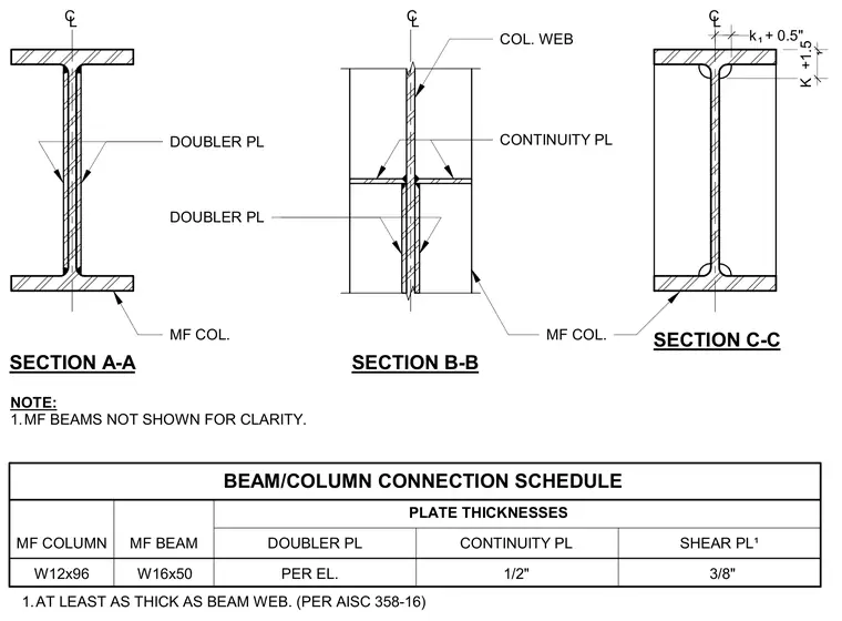
This structural detail provides a schedule and cross-sections for moment frame beam-to-column connections using wide-flange shapes such as a W12x96 column and W16x50 beam. Section A-A and Section B-M illustrate the placement of doubler plates and continuity plates relative to the column web and flanges. Section C-C outlines dimensional parameters including k1 + 0.5 inches and k + 1.5 inches. Plate thicknesses are specified with continuity plates at one-half inch and shear plates at three-eighths of an inch, while doubler plates are determined per elevation in accordance with AISC 358-16 standards.
MF COLUMN MF BEAM DOUBLER PL CONTINUITY PL SHEAR PL¹ BEAM/COLUMN CONNECTION SCHEDULE PER EL. W12x96 W16x50 1/2" 3/8" PLATE THICKNESSES k + 0.5" ¹ K +1.5 ¹ SECTION C-C NOTE: 1.MF BEAMS NOT SHOWN FOR CLARITY. MF COL. SECTION A-A SECTION B-B 1.AT LEAST AS THICK AS BEAM WEB. (PER AISC 358-16) MF COL. CL CL CL COL. WEB CONTINUITY PL DOUBLER PL DOUBLER PL
Members view this detail in full resolution, download the CAD files (SVG, PDF), and can adapt it in the built-in CAD editor — export DXF, DWG, or PDF.
Start membership