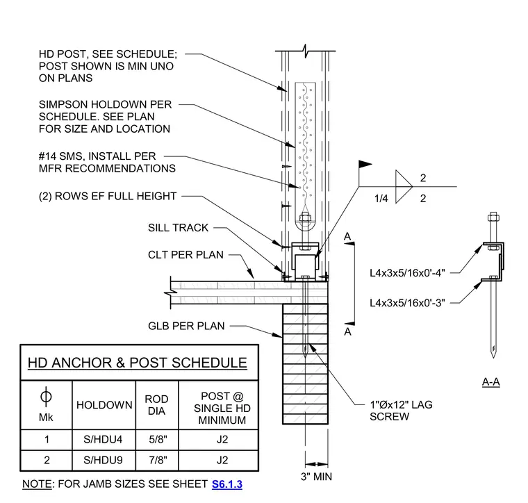
This drawing provides a holdown anchor and post schedule alongside a typical wood-framed wall base detail. A Simpson holdown connects to a holdown post sized per plan, secured with number fourteen self-tapping metal screws installed per manufacturer recommendations. The assembly ties into a sill track with two rows of fasteners, bearing on cross-laminated timber and glulam members specified per plan. A one-inch diameter by twelve-inch lag screw anchors the base into the foundation assembly with a three-inch minimum embedment. Section A-A details the angle and fastener configuration using L4x3x5/16 angles.
HD ANCHOR & POST SCHEDULE HOLDOWN ROD DIA S/HDU4 5/8" J2 J2 7/8" S/HDU9 POST @ SINGLE HD MINIMUM SIMPSON HOLDOWN PER SCHEDULE. SEE PLAN FOR SIZE AND LOCATION #14 SMS, INSTALL PER MFR RECOMMENDATIONS (2) ROWS EF FULL HEIGHT SILL TRACK HD POST, SEE SCHEDULE; POST SHOWN IS MIN UNO ON PLANS Mk 1 2 CLT PER PLAN GLB PER PLAN 3" MIN NOTE: FOR JAMB SIZES SEE SHEET S6.1.3 1/4 2 2 A-A L4x3x5/16x0'-3" L4x3x5/16x0'-4" 1"Øx12" LAG SCREW A A
Members view this detail in full resolution, download the CAD files (SVG, PDF), and can adapt it in the built-in CAD editor — export DXF, DWG, or PDF.
Start membership