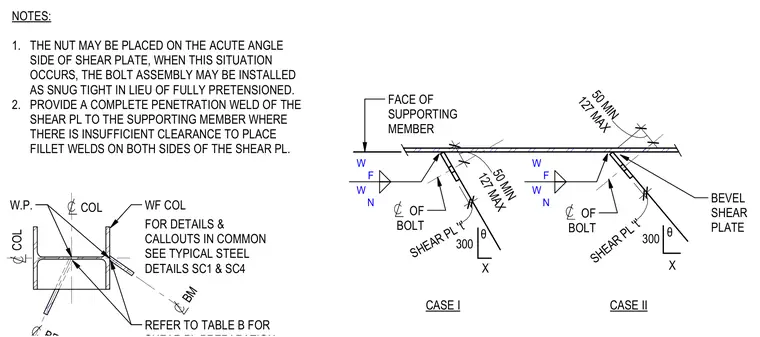
A bevel shear plate connects a wide-flange beam to a supporting member at an angle, utilizing a shear plate designated with thickness t and dimensioned with a maximum of 127 millimeters and a minimum of 50 millimeters. Case I and Case II illustrate the orientation and weld symbols for the shear plate, specifying fillet welds and complete penetration welds where clearance is insufficient. Notes permit the nut to be placed on the acute angle side of the shear plate, allowing the bolt assembly to be installed as snug tight instead of fully pretensioned when this condition occurs.
NOTES: 1. THE NUT MAY BE PLACED ON THE ACUTE ANGLE SIDE OF SHEAR PLATE, WHEN THIS SITUATION OCCURS, THE BOLT ASSEMBLY MAY BE INSTALLED AS SNUG TIGHT IN LIEU OF FULLY PRETENSIONED. 2. PROVIDE A COMPLETE PENETRATION WELD OF THE SHEAR PL TO THE SUPPORTING MEMBER WHERE THERE IS INSUFFICIENT CLEARANCE TO PLACE FILLET WELDS ON BOTH SIDES OF THE SHEAR PL. C L COL C L COL C L BM WF COL REFER TO TABLE B FOR FOR DETAILS & CALLOUTS IN COMMON SEE TYPICAL STEEL DETAILS SC1 & SC4 W.P. FACE OF SUPPORTING MEMBER OF BOLT C L SHEAR PL 't' 300 X θ CASE I 127 MAX 50 MIN W F W N W F W N OF BOLT C L SHEAR PL 't' 300 X θ 127 MAX 50 MIN CASE II BEVEL SHEAR PLATE
Members view this detail in full resolution, download the CAD files (SVG, PDF), and can adapt it in the built-in CAD editor — export DXF, DWG, or PDF.
Start membership