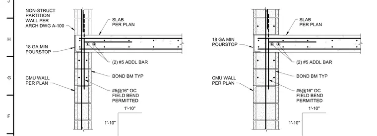
A reinforced concrete slab bears directly onto a concrete masonry unit wall constructed per plan, utilizing an eighteen gauge minimum pour stop at the slab edge. Vertical reinforcement consists of number five bars spaced at sixteen inches on center with field bends permitted, supplemented by two additional number five bars extending one foot ten inches. A non-structural partition wall connects above the slab edge as specified in architectural drawings.
SLAB PER PLAN 18 GA MIN POURSTOP BOND BM TYP #5@16" OC FIELD BEND PERMITTED CMU WALL PER PLAN (2) #5 ADDL BAR 1'-10" 1'-10" SLAB PER PLAN NON-STRUCT PARTITION WALL PER ARCH DWG A-100 18 GA MIN POURSTOP BOND BM TYP #5@16" OC FIELD BEND PERMITTED CMU WALL PER PLAN (2) #5 ADDL BAR 1'-10" 1'-10" J G H F
Members view this detail in full resolution, download the CAD files (SVG, PDF), and can adapt it in the built-in CAD editor — export DXF, DWG, or PDF.
Start membership