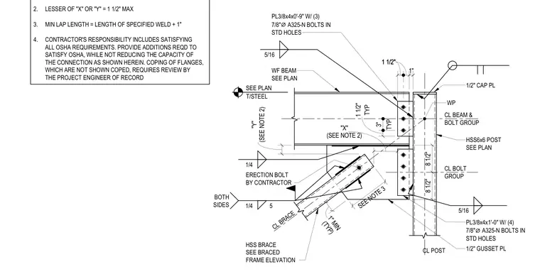
A steel braced frame connection between a wide-flange beam and an HSS6x6 post incorporates an HSS brace welded to a half-inch gusset plate. The beam connects to the post using top and bottom clip plates, specifically a 3/8-inch by 4-inch by 9-inch plate with three 7/8-inch diameter A325-N bolts at the top and a similar 1-foot long plate with four 7/8-inch diameter A325-N bolts at the bottom. A half-inch cap plate is positioned at the top of the HSS post. Fillet welds of 1/4-inch and 5/16-inch sizes secure the gusset plate and brace assembly as specified on the drawings. Erection bolts are provided by the contractor to temporarily hold the brace during assembly, maintaining specified clearances and lap lengths.
2. LESSER OF "X" OR "Y" = 1 1/2" MAX 3. MIN LAP LENGTH = LENGTH OF SPECIFIED WELD + 1" 4. CONTRACTOR'S RESPONSIBILITY INCLUDES SATISFYING ALL OSHA REQUIREMENTS. PROVIDE ADDITIONS REQD TO SATISFY OSHA, WHILE NOT REDUCING THE CAPACITY OF THE CONNECTION AS SHOWN HEREIN. COPING OF FLANGES, WHICH ARE NOT SHOWN COPED, REQUIRES REVIEW BY THE PROJECT ENGINEER OF RECORD CL BEAM & BOLT GROUP WP HSS BRACE SEE BRACED FRAME ELEVATION CL BOLT GROUP HSS6x6 POST SEE PLAN WF BEAM SEE PLAN "Y" (SEE NOTE 2) CL BRACE 8 1/2" 8 1/2" ERECTION BOLT BY CONTRACTOR 1/2" GUSSET PL PL3/8x4x1'-0" W/ (4) 7/8" ⌀ A325-N BOLTS IN STD HOLES 1/2" CAP PL 1" 1 1/2" 1 1/2" TYP 3" TYP 1 1/2" (TYP) 1" MIN PL3/8x4x0'-9" W/ (3) 7/8" ⌀ A325-N BOLTS IN STD HOLES CL POST 5/16 1/4 5/16 1/4 5 BOTH SIDES (SEE NOTE 2) "X" T/STEEL SEE PLAN SEE NOTE 3
Members view this detail in full resolution, download the CAD files (SVG, PDF), and can adapt it in the built-in CAD editor — export DXF, DWG, or PDF.
Start membership