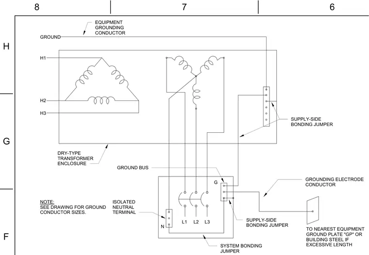
This electrical schematic details the grounding configuration for a dry-type transformer enclosure. An equipment grounding conductor connects to the transformer enclosure ground bus, while supply-side bonding jumpers tie the transformer windings to the ground bus and isolated neutral terminal. A system bonding jumper connects the neutral terminal to the ground bus, which extends to a grounding electrode conductor tied to the nearest equipment ground plate or building steel. An accompanying note directs the builder to check the drawings for specific ground conductor sizes.
N G GROUND H1 H3 H2 L2 L1 L3 EQUIPMENT GROUNDING CONDUCTOR TO NEAREST EQUIPMENT GROUND PLATE "GP" OR BUILDING STEEL IF EXCESSIVE LENGTH ISOLATED NEUTRAL TERMINAL SUPPLY-SIDE BONDING JUMPER DRY-TYPE TRANSFORMER ENCLOSURE GROUND BUS NOTE: SEE DRAWING FOR GROUND CONDUCTOR SIZES. GROUNDING ELECTRODE CONDUCTOR SYSTEM BONDING JUMPER SUPPLY-SIDE BONDING JUMPER 6 7 8 F G H
Members view this detail in full resolution, download the CAD files (SVG, PDF), and can adapt it in the built-in CAD editor — export DXF, DWG, or PDF.
Start membership