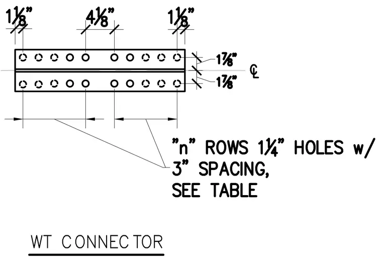
The WT connector profile features rows of one-and-one-quarter-inch diameter holes spaced at three inches on center, with specific edge and gauge dimensions defined relative to the centerline. Edge distances measure one-and-one-eighth inches from the ends, and transverse gauge dimensions measure one-and-seven-eighths inches from the centerline to each row. The total number of rows is variable as indicated by the variable designation, with final quantities sized per the structural schedule. Dimensions are explicitly called out for fabrication layout and shop drawing verification.
Members view this detail in full resolution, download the CAD files (SVG, PDF), and can adapt it in the built-in CAD editor — export DXF, DWG, or PDF.
Start membership