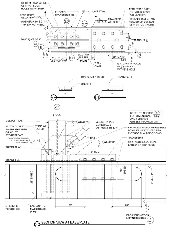
A buckling-restrained brace connection is anchored into a reinforced concrete foundation. The assembly incorporates a three-and-a-half-inch Grade 50 base plate with eight one-and-a-half-inch diameter ASTM F1554 Grade 105 anchor bolts installed in oversized holes with washers. A gusset plate connects to the brace, leaving the wide flange tip and k-regions unwelded. Additional reinforcement includes number nine bars with one-hundred-eighty-degree hooks and stirrups sized per the schedule, with one-inch minimum compressible foam provided on each side where the brace extends below the top of the slab.
£Ó CAST IN PLACE W/ (2) MIN 2"ø WITNESS HOLE SECTION VIEW AT BASE PLATE COL PER PLAN £1Ëx5Ï TRANSFER £ ES (8) 1Ï"ø F1554 GR 105 HEADED OR DBL NUT AB IN È" OVS HOLES WASHER £1x4 SQ TYP( DO NOT WELD) (8) 1Ï"ø F1554 GR105 AB IN Ì"ø OVS HOLES W/ WASHER BASE £3Ï GR50 Ï NOTCH GUSSET WHERE EXPOSED OR ADJ TO STORE FRONT C-C C-C STIRRUPS PER SCHED DO NOT WELD FLANGE TIP OR k REGIONS AT WIDE FLANGE ADDL REINF BARS (NOT ALL SHOWN FOR CLARITY) TRANSFER £ FOR INFORMATION NOT NOTED SEE TRANSFER WELD TYP TRANSFER WELD TYP B-B A-A S t L t S t L t /2 1 S6.2 2.3 B TRANSFER £ TRANSFER £ BYND SHEAR £ REFER TO SECHED FOR DIMENSIONS AND FURTHER GUSSET INFORMATION 9 S6.2 TYP 2 1/2" 1" TYP 8" TYP MIN 3" 3" SYM ABOUT ¢ TYP 6" TYP 4" 2" MAX 1" MIN MIN 4" 4" MIN SIZE FOR GUSSET TYP EQ TYP EQ CJP DCW B-B A-A TOP OF SLAB ¢ COL TOP OF FDN 2" HSG WP GUSSET £ PER COREBRACE DETAILS, SEE S3.5 BRB TYP 3" CLR 2" CLR, TYP (8) #9 ADDITIONAL REINF BARS WITH 180° HK EE ¢ L WELD "H" L WELD "V" TYP 6" 26" 26" TYP 2" TYP 3" PROVIDE 1" MIN COMPRESSIBLE FOAM EA SIDE WHERE BRB EXTENDS BLW TOP OF SLAB NOTCH 1/2" MIN AT EMBED £ TO MATCH BASE £ MIN 28" EMBED EMBED 16" 2.3
Members view this detail in full resolution, download the CAD files (SVG, PDF), and can adapt it in the built-in CAD editor — export DXF, DWG, or PDF.
Start membership