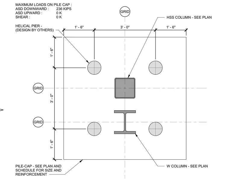
Four helical piers, designated as design by others, support the pile cap. The cap accommodates a central hollow structural section column and a wide-flange column, both sized per plan. Piers are positioned at the corners of a three-foot by three-foot grid, each located one foot six inches from the centerlines. Pile cap dimensions, size, and reinforcement are determined per project plans and schedules. The assembly supports a maximum allowable stress design downward load of 236 kips, with zero upward load and zero shear.
Members view this detail in full resolution, download the CAD files (SVG, PDF), and can adapt it in the built-in CAD editor — export DXF, DWG, or PDF.
Start membership