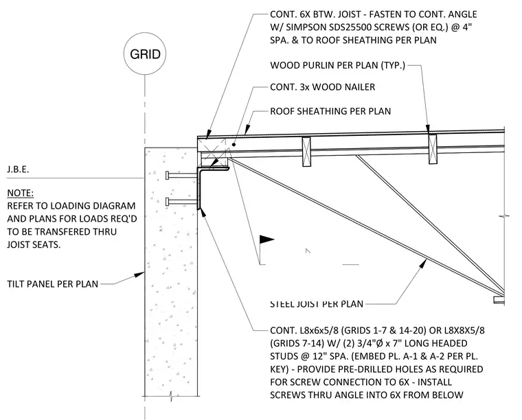
This assembly features a steel joist supported by a continuous L8x6x5/8 or L8x8x5/8 steel angle embedded into a tilt-up concrete panel. The angle is anchored to the concrete with two 3/4-inch diameter by 7-inch long headed studs spaced at 12 inches on center. A continuous 6x wood member is fastened to the horizontal leg of the angle using Simpson SDS25500 screws spaced at 4 inches on center, with screws installed from below through the angle. A 3x wood nailer is secured atop the 6x member, supporting the roof sheathing as specified in the plans.
F GRID TILT PANEL PER PLAN ROOF SHEATHING PER PLAN J.B.E. NOTE: REFER TO LOADING DIAGRAM AND PLANS FOR LOADS REQ'D TO BE TRANSFERED THRU JOIST SEATS. 1/4 3 CONT. 3x WOOD NAILER STEEL JOIST PER PLAN CONT. L8x6x5/8 (GRIDS 1-7 & 14-20) OR L8X8X5/8 (GRIDS 7-14) W/ (2) 3/4"Ø x 7" LONG HEADED STUDS @ 12" SPA. (EMBED PL. A-1 & A-2 PER PL. KEY) - PROVIDE PRE-DRILLED HOLES AS REQUIRED FOR SCREW CONNECTION TO 6X - INSTALL SCREWS THRU ANGLE INTO 6X FROM BELOW WOOD PURLIN PER PLAN (TYP.) CONT. 6X BTW. JOIST - FASTEN TO CONT. ANGLE W/ SIMPSON SDS25500 SCREWS (OR EQ.) @ 4" SPA. & TO ROOF SHEATHING PER PLAN SECTION S4.2 3/4" = 1'-0" 05
Members view this detail in full resolution, download the CAD files (SVG, PDF), and can adapt it in the built-in CAD editor — export DXF, DWG, or PDF.
Start membership