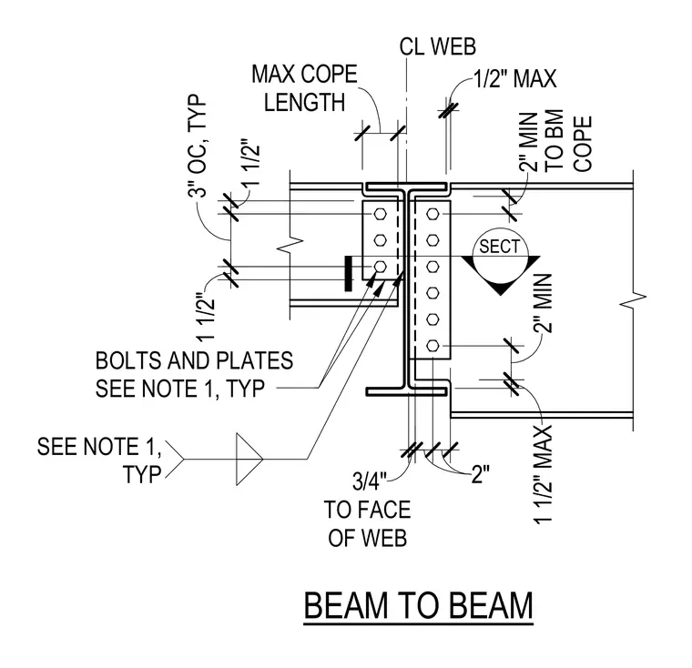
A supported steel beam connects to the web of a supporting steel beam using bolted connection plates typical per project notes. The supported beam features a top and bottom flange cope with specified maximum cope lengths and clearances to the web face. Fastener patterns follow standard spacing dimensions with three-inch on-center spacing typical. Connection plates and bolts are sized per structural notes.
SECT SEE NOTE 1 1/2" MAX 3/4" BOLTS AND PLATES SEE NOTE 1, TYP SEE NOTE 1, TYP TO BM COPE LENGTH MAX COPE CL WEB BEAM TO BEAM TO FACE OF WEB 1 1/2" MAX 2" MIN 2"2" 2" MIN 3" OC, TYP 6" 1 1/2" 1 1/2"
Members view this detail in full resolution, download the CAD files (SVG, PDF), and can adapt it in the built-in CAD editor — export DXF, DWG, or PDF.
Start membership