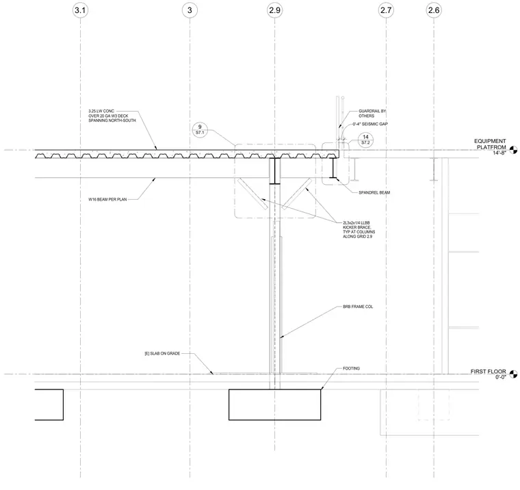
An elevated equipment platform at fourteen feet eight inches above the first floor features a three and a quarter inch lightweight concrete topping over a twenty gauge W3 metal deck spanning north-south, supported by a W16 beam sized per plan. At the perimeter, a spandrel beam aligns with a zero to four inch seismic gap adjacent to a guardrail provided by others. A buckling-restrained braced frame column extends down from the platform level to a footing below the existing slab on grade, stabilized by double angle kicker braces composed of two 3x2x1/4 angles with long legs back-to-back, typical at columns along grid line two point nine.
FIRST FLOOR 0'-0" EQUIPMENT PLATFROM 14'-8" 3 2.6 2.7 3.1 2.9 3.25 LW CONC OVER 20 GA W3 DECK SPANNING NORTH-SOUTH W16 BEAM PER PLAN GUARDRAIL BY OTHERS SPANDREL BEAM 2L3x2x1/4 LLBB KICKER BRACE, TYP AT COLUMNS ALONG GRID 2.9 BRB FRAME COL [E] SLAB ON GRADE FOOTING 0'-4" SEISMIC GAP S7.2 14 S7.1 9
Members view this detail in full resolution, download the CAD files (SVG, PDF), and can adapt it in the built-in CAD editor — export DXF, DWG, or PDF.
Start membership