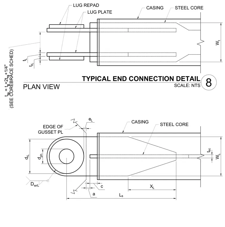
An end connection for a buckling-restrained brace appears in plan and elevation views. The assembly consists of a central steel core encased in a steel casing, terminating in dual lug plates with reinforcing repads. Dimensioning parameters define the core width, casing dimensions, edge distances, and plate thicknesses according to the core brace schedule. The design incorporates pin holes and gusset plate interfaces for integration into the structural lateral force-resisting system.
EDGE OF GUSSET PL W t t rL t L t tg = t g +2t rg +1/4" (SEE COREBRACE SCHED) L s a c W L X L t sc e L d rL d ph STEEL CORE D wrL CASING LUG PLATE LUG REPAD CASING STEEL CORE 8 TYPICAL END CONNECTION DETAIL SCALE: NTS PLAN VIEW
Members view this detail in full resolution, download the CAD files (SVG, PDF), and can adapt it in the built-in CAD editor — export DXF, DWG, or PDF.
Start membership