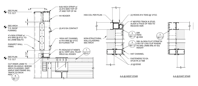
Out-of-plane support for parapet wall framing bearing on a cross-laminated timber roof. A sixteen-gauge hat channel is secured with number ten self-tapping sheet metal screws at twelve inches on center to each flange, spanning the non-structural wall cladding. A sixteen-gauge plate measuring three by five inches is fillet welded along all edges at the centerline of the vertical leg to the structural support. Behind architectural cladding, the angle is omitted and the sill track is framed directly to the deck. Four-inch nested track and studs align with the face of the hollow structural section column to receive the header, utilizing number fourteen Teks screws.
16GA HAT CHANNEL w/ #10 SMS @ 12"CC EA FLANGE TYP (2) #12 EA CONTACT 1 S5.6.1 6 1/2" T.O. CLT SEE PLAN T.O. ROOF FURRING SEE ARCH PARAPET WALL FRMG A A HAT CHANNEL NON-STRUCTURAL WALL/CLADDING SEE ARCH J2 @ EDGE FASTENERS TO EA STUD IN J2 T&B A-A @ WEST STAIR A-A @ EAST STAIR 3 S6.1.3 (2) ROWS #14 TEKS @ 12"CC 4" NESTED TRACK & STUD, ALIGN w/ FACE OF HSS TO RECEIVE HDR 3 S6.1.3 SIM TEKS @ HSS T.O. CLT SEE PLAN CUT INNER JAMB TO BEAR ON ANGLE. BHEIND ARCH CLADDING, OMIT ANGLE AND FRAME SILL TRACK TO DECK PER 6 S6.1.1 1" 4"x18GA STRAP w/ #10 SMS @ 6"CC TO EA JAMB NS& FS H4 HEADER 6x6x16GA STRAP w/ (3) #10 SMS TOP OF JT AND TOP OF H4 3 S6.1.3 SIM, 6x16GA FLAT STRAP IN LIEU OF L2X2 CLIP WHERE H4 AND JAMB ARE AT EQ HEIGHT HSS COL PER PLAN PL16GAx3x0'-5" NS&FS @ CL VERT LEG. FILLET WELD ALL EDGES
Members view this detail in full resolution, download the CAD files (SVG, PDF), and can adapt it in the built-in CAD editor — export DXF, DWG, or PDF.
Start membership