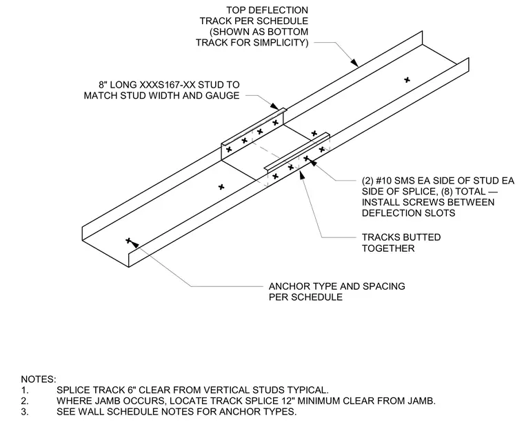
Two lengths of top deflection track are butted together and joined using an eight-inch long stud segment matching the width and gauge of the track. Two number ten self-tapping sheet metal screws are installed on each side of the stud and each side of the splice for a total of eight fasteners. Screws are installed between the deflection slots of the top track. The splice is located six inches clear from vertical studs typically, and twelve inches minimum clear from any jamb.
ANCHOR TYPE AND SPACING PER SCHEDULE NOTES: 1. SPLICE TRACK 6" CLEAR FROM VERTICAL STUDS TYPICAL. 2. WHERE JAMB OCCURS, LOCATE TRACK SPLICE 12" MINIMUM CLEAR FROM JAMB. 3. SEE WALL SCHEDULE NOTES FOR ANCHOR TYPES. TRACKS BUTTED TOGETHER 8" LONG XXXS167-XX STUD TO MATCH STUD WIDTH AND GAUGE (2) #10 SMS EA SIDE OF STUD EA SIDE OF SPLICE, (8) TOTAL — INSTALL SCREWS BETWEEN DEFLECTION SLOTS TOP DEFLECTION TRACK PER SCHEDULE (SHOWN AS BOTTOM TRACK FOR SIMPLICITY)
Members view this detail in full resolution, download the CAD files (SVG, PDF), and can adapt it in the built-in CAD editor — export DXF, DWG, or PDF.
Start membership