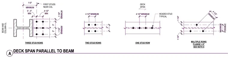
Composite steel beam layout detailing headed shear stud placement and spacing configurations for metal deck spanning parallel to the supporting steel beam. Single, double, and triple stud rows are positioned on the beam flange relative to the beam and column centerline. Specified dimensions include a one-foot minimum from the first studs near the column, four-and-one-half-inch minimum spacings, and edge clearances of one-and-one-quarter inches. Additional configurations address narrow flanges less than six inches with multiple stud rows.
TWO STUD ROWS 3" ONE STUD ROW FIRST STUDS NEAR COL MINIMUM 1 1/4" 3" 3" MINIMUM 1 1/4" MINIMUM 1'-0" MIN 0' - 4" THREE STUD ROWS DECK SPAN MULTIPLE ROWS FLANGE < 6" SEE NOTE 6 POSSIBLE MAXIMUM MINIMUM 4 1/2" BEAM AND COLUMN CL 1 1/4" MIN 4 1/2" 4 1/2" MINIMUM 4 1/2" MINIMUM HEADED STUD TYPICAL 1 1/4" A DECK SPAN PARALLEL TO BEAM TWO STUD ROWS 3" ONE STUD ROW FIRST STUDS NEAR COL MINIMUM 1 1/4" 3" 3" MINIMUM 1 1/4" MINIMUM 1'-0" MIN 0' - 4" THREE STUD ROWS DECK SPAN MULTIPLE ROWS FLANGE < 6" SEE NOTE 6 POSSIBLE MAXIMUM MINIMUM 4 1/2" BEAM AND COLUMN CL 1 1/4" MIN 4 1/2" 4 1/2" MINIMUM 4 1/2" MINIMUM HEADED STUD TYPICAL 1 1/4" A DECK SPAN PARALLEL TO BEAM
Members view this detail in full resolution, download the CAD files (SVG, PDF), and can adapt it in the built-in CAD editor — export DXF, DWG, or PDF.
Start membership