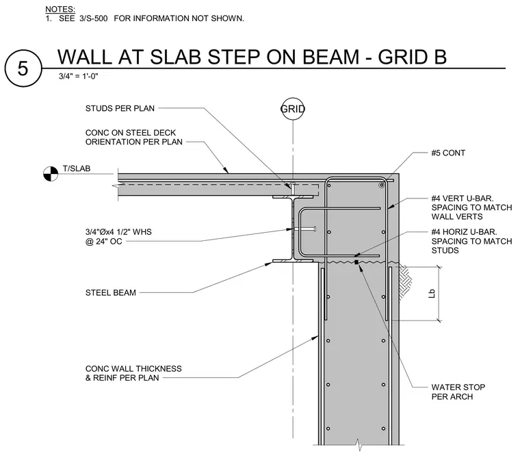
A concrete wall connects to a concrete slab on a steel beam at a grid line. The assembly features a concrete wall with thickness and reinforcement sized per plan, tied to the steel beam using three-quarter-inch by four-and-a-half-inch welded headed studs spaced at twenty-four inches on center. A concrete-on-steel-deck floor system bears on the steel beam, secured with studs per plan. Reinforcing includes a continuous number five bar at the top corner, number four vertical U-bars spaced to match the wall verticals, and number four horizontal U-bars spaced to match the studs. A water stop is installed per architectural specifications, and additional information is referenced on sheet three of S-500.
GRID T/SLAB NOTES: 1. SEE FOR INFORMATION NOT SHOWN. 3/S-500 STEEL BEAM CONC WALL THICKNESS & REINF PER PLAN #5 CONT CONC ON STEEL DECK ORIENTATION PER PLAN #4 VERT U-BAR. SPACING TO MATCH WALL VERTS WATER STOP PER ARCH 3/4"Øx4 1/2" WHS @ 24" OC STUDS PER PLAN #4 HORIZ U-BAR. SPACING TO MATCH STUDS Lb 3/4" = 1'-0" 5 WALL AT SLAB STEP ON BEAM - GRID B
Members view this detail in full resolution, download the CAD files (SVG, PDF), and can adapt it in the built-in CAD editor — export DXF, DWG, or PDF.
Start membership