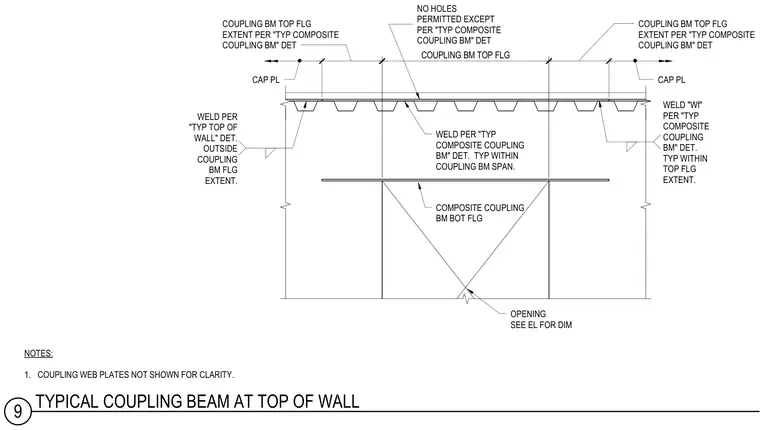
A structural steel coupling beam frames at the top of a wall with a cap plate. The coupling beam top flange extent and cap plate welds are detailed per standard composite coupling beam requirements. Welds within the coupling beam span and outside the flange extent conform to designated top of wall and composite coupling beam details. No unauthorized holes are permitted except as specified in the standard details. The composite coupling beam bottom flange incorporates an opening dimensioned per the structural elevations, with coupling web plates omitted for clarity.
NOTES: 1. COUPLING WEB PLATES NOT SHOWN FOR CLARITY. COUPLING BM TOP FLG 18" 18" COUPLING BM TOP FLG EXTENT PER "TYP COMPOSITE COUPLING BM" DET COUPLING BM TOP FLG EXTENT PER "TYP COMPOSITE COUPLING BM" DET CAP PL CAP PL WELD PER "TYP COMPOSITE COUPLING BM" DET. TYP WITHIN COUPLING BM SPAN. WELD "Wf" PER "TYP COMPOSITE COUPLING BM" DET. TYP WITHIN TOP FLG EXTENT. WELD PER "TYP TOP OF WALL" DET. OUTSIDE COUPLING BM FLG EXTENT. NO HOLES PERMITTED EXCEPT PER "TYP COMPOSITE COUPLING BM" DET COMPOSITE COUPLING BM BOT FLG OPENING SEE EL FOR DIM 9 TYPICAL COUPLING BEAM AT TOP OF WALL
Members view this detail in full resolution, download the CAD files (SVG, PDF), and can adapt it in the built-in CAD editor — export DXF, DWG, or PDF.
Start membership