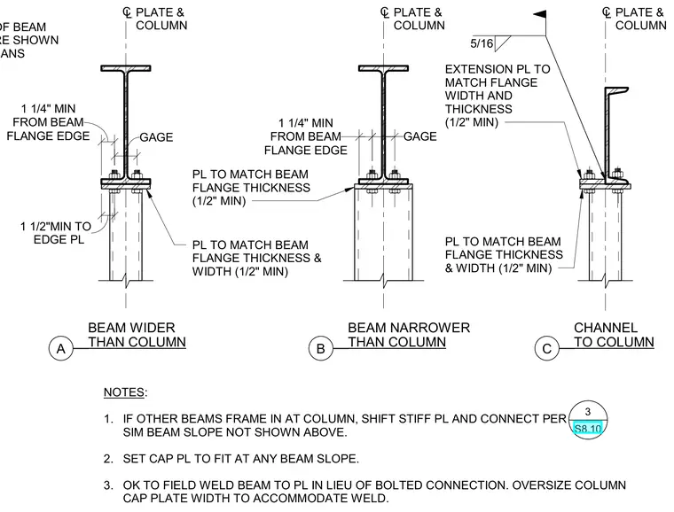
These structural details illustrate beam-to-column cap plate connections for three conditions: a beam wider than the column, a beam narrower than the column, and a channel connected to a column. Each assembly utilizes a column cap plate sized to match the beam flange thickness and width with a one-half inch minimum dimension. Bolted connections secure the beam flanges to the cap plate, with alternate provisions permitting field welding of the beam to the plate by oversizing the column cap plate width. Notes outline adjustments required when other framing beams intersect the column and provide allowances for sloped beam conditions.
NOTES: 1. IF OTHER BEAMS FRAME IN AT COLUMN, SHIFT STIFF PL AND CONNECT PER SIM BEAM SLOPE NOT SHOWN ABOVE. 2. SET CAP PL TO FIT AT ANY BEAM SLOPE. 3. OK TO FIELD WELD BEAM TO PL IN LIEU OF BOLTED CONNECTION. OVERSIZE COLUMN CAP PLATE WIDTH TO ACCOMMODATE WELD. PL TO MATCH BEAM FLANGE THICKNESS & WIDTH (1/2" MIN) EXTENSION PL TO MATCH FLANGE WIDTH AND THICKNESS (1/2" MIN) C L PLATE & COLUMN GAGE FLANGE EDGE 1 1/4" MIN FROM BEAM C L PLATE & COLUMN PL TO MATCH BEAM FLANGE THICKNESS (1/2" MIN) PL TO MATCH BEAM FLANGE THICKNESS & WIDTH (1/2" MIN) FLANGE EDGE 1 1/4" MIN FROM BEAM EDGE PL 1 1/2"MIN TO C L PLATE & COLUMN END OF BEAM WHERE SHOWN ON PLANS __ __ A THAN COLUMN BEAM WIDER __ __ B THAN COLUMN BEAM NARROWER __ __ C TO COLUMN CHANNEL 5/16 GAGE 3 S8.10
Members view this detail in full resolution, download the CAD files (SVG, PDF), and can adapt it in the built-in CAD editor — export DXF, DWG, or PDF.
Start membership