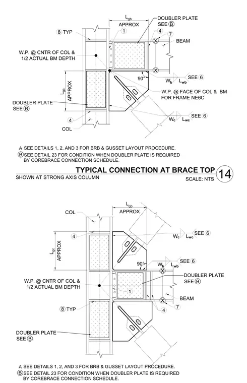
A typical connection for a buckling-restrained brace at both the top and bottom locations along a strong-axis steel column and intersecting beam incorporates gusset plates connected to the column and beam flanges, with work points defined at the center of the column and half-actual beam depth as well as at the face of the column and beam for frame NE6C. Doubler plates are included per the corebrace connection schedule where required, and layout procedures reference subsidiary details for precise positioning. Weld symbols and plate dimensions are designated with variable notation to accommodate specific engineering requirements.
COL 4 L gb APPROX 6 SEE BEAM 90° L gc APPROX 6 SEE W c W b W.P. @ CNTR OF COL & 1/2 ACTUAL BM DEPTH X X 1 4 7 L wc L wb 8 TYP SEE DETAIL 23 FOR CONDITION WHEN DOUBLER PLATE IS REQUIRED BY COREBRACE CONNECTION SCHEDULE. TYPICAL CONNECTION AT BRACE TOP SCALE: NTS SHOWN AT STRONG AXIS COLUMN SEE DETAILS 1, 2, AND 3 FOR BRB & GUSSET LAYOUT PROCEDURE. B DOUBLER PLATE B SEE DOUBLER PLATE B SEE A L gc APPROX COL 4 L gb APPROX 4 6 SEE W b BEAM 90° 6 SEE W c 1 W.P. @ CNTR OF COL & 1/2 ACTUAL BM DEPTH X X 7 L wc L wb 8 TYP SEE DETAIL 23 FOR CONDITION WHEN DOUBLER PLATE IS REQUIRED BY COREBRACE CONNECTION SCHEDULE. SEE DETAILS 1, 2, AND 3 FOR BRB & GUSSET LAYOUT PROCEDURE. B DOUBLER PLATE B SEE DOUBLER PLATE B SEE A 14 W.P. @ FACE OF COL & BM FOR FRAME NE6C
Members view this detail in full resolution, download the CAD files (SVG, PDF), and can adapt it in the built-in CAD editor — export DXF, DWG, or PDF.
Start membership