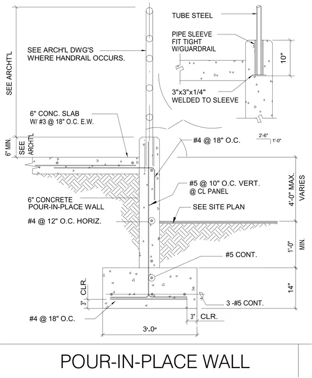
A six-inch concrete pour-in-place wall extends upward from a fourteen-inch thick by three-foot wide continuous concrete strip footing reinforced with three number five continuous bars at the bottom and number four bars at eighteen inches on center. The wall stem features number five vertical bars at ten inches on center at the centerline of the panel, combined with number four horizontal bars at twelve inches on center. A six-inch concrete slab ties into the wall with number three reinforcing bars at eighteen inches on center each way. At the top of the wall, a structural tube steel pipe sleeve is fitted tightly with a guardrail, welded to a three-inch by three-inch by quarter-inch plate, and embedded ten inches into the concrete.
POUR-IN-PLACE WALL 3 -#5 CONT. #5 CONT. W/ #3 @ 18" O.C. E.W. 6" CONC. SLAB #4 @ 18" O.C. POUR-IN-PLACE WALL 4'-0" MAX. 3'-0" 3" 3" 14" SEE ARCH'L DWG'S SEE ARCHT'L WHERE HANDRAIL OCCURS. #4 @ 12" O.C. HORIZ. 6" CONCRETE ARCHT'L 6" MIN. SEE 10" MIN. VARIES 1'-0" CLR. CLR. @ CL PANEL 3"x3"x1/4" WELDED TO SLEEVE #5 @ 10" O.C. VERT. SEE SITE PLAN #4 @ 18" O.C. TUBE STEEL PIPE SLEEVE 2'-6" 1'-0" FIT TIGHT W/GUARDRAIL
Members view this detail in full resolution, download the CAD files (SVG, PDF), and can adapt it in the built-in CAD editor — export DXF, DWG, or PDF.
Start membership